Wednesday 30 January 2013

Email Architecture


One of the popular Internet services is electronic mail (e-mail). It is a process of exchanging digital messages from a person to one or more recipients. Here I will provide an overview of how email systems are organized and what they can do. The architecture of the email system is shown in the below figure,
Email Architecture
Email Architecture
UA: user agent
MTA: message transfer agent
MAA: message access agent

Tuesday 29 January 2013

Tunneling Network

Tunnels are a mechanism used to send unsupported protocols across diverse networks. Tunneling is the encapsulation of packet from one protocol to another one at the same or higher layer. Virtual Private Networks (VPN) use advanced encryption and tunneling to secure, end-to-end, private network connections over a third-party network. 
As an example, consider an international organization with an IPv6 network in New York, an IPv6 network in Paris and need to connect between the offices via the IPv4 Internet. The IPv6 packets are not able to travel through an IPv4 network directly.

Sunday 27 January 2013

IEEE Network Standards


IEEE 802.x Standards 

IEEE 802 refers to a family of IEEE standards dealing with local area networks and metropolitan area networks.

Name
Description
IEEE 802.1
Bridging (networking) and Network Management
IEEE 802.2
Logical Link Control (LLC)
IEEE 802.3
Ethernet
IEEE 802.4
Token bus
IEEE 802.5
Defines the MAC layer for a Token Ring

Satellite Network


Communication Satellite 

A communications satellite or Comsat is an artificial satellite sent to space for the purpose of telecommunications. A satellite needs to have an orbit the path in which it travels around the Earth. The orbit can be equatorial, inclined, or polar.
Equatorial orbit satellite
inclined orbit satellite
Inclined orbit satellite


Thursday 24 January 2013

Unguided Transmission Media

Unguided media transfer electromagnetic waves without using a physical conductor. When electrons move, they produce electromagnetic waves that can transport through the free space. In vacuum, all electromagnetic waves move at the same speed. Unguided signals can travel from source to target in different ways: grounded propagation, sky propagation and line-of-sight propagation.
In ground wave propagation, radio waves travel along the surface of the earth with a frequency less than 2 MHz.  
In sky propagation, signals propagated by refraction in the ionosphere. Support frequency in between 2 MHz and 30 MHz.
In line-of-sight propagation signals are transmitted in straight lines from antenna to antenna by using frequency greater than 30 MHz.


Wireless transmission can divide into three broad classes: radio waves, microwaves, and infrared waves

Optical Fiber

An optical fiber is a thin, flexible medium capable of conducting optical rays.  Optical fibers use reflection to guide light through a channel. In optical fibers, a cladding of less dense glass or plastic surrounds a glass or plastic core. Due to the difference between the density of core and cladding, the light moving through the core is reflected off the cladding instead of being refracted into it.
Optical fiber
Optical fiber

Propagation Mode
According to the mode of propagation, optical fiber is classified into two: single-mode and multi-mode. 
Optical fiber propagation mode

Multi-mode

Multimode fiber optic cable has a large diameter core that allows multiple modes of light to propagate. How these different light beams are move within the optical fiber depends on the construction of the core.

Coaxial Cable

Coaxial cable carries signals of higher frequency ranges than twisted pair cable. The coaxial cable has a central core conductor of solid usually copper enclosed in an insulating sheath, which is encased in an outer metallic conductor. The outer metallic wrapping not only serve as a shield against noise but it also act as a second conductor, which completes the circuit.
Coaxial cable
Coaxial Cable

Coaxial cables are categorized by their radio government (RG) ratings as shown below,

Transmission Media

A transmission media can be defined as anything that carries data from one place to another. Transmission media broadly divided into two:  guided media and unguided media.

Transmission Media
Transmission Media

Guided Media

Guided media are those that provide a channel from one device to another. Here we consider three guided Medias, twisted pair cable, coaxial cable and fiber optic cable.

Twisted Pair Cable

A twisted pair cable consists of two insulated copper wires. Typically, the thickness of each wire is 1 mm. One of the wires is used to carry signals to the receiver, and the other is used only as a ground reference.

Shannon Capacity and Nyquist Bit Rate

The rate at which data can be transmitted over a given communication channel, under given conditions, is referred as the channel capacity.
There exist two formulas for calculate theoretical maximum data rate. Nyquist bit rate for noiseless channel and Shannon capacity for noisy channel.

Nyquist Bit Rate

The Nyquist bit rate formula is use to calculate the theoretical maximum bit rate.
                                  Bit rate=2*bandwidth*log2L
Where bandwidth is the bandwidth of the channel, ‘L’ is the signal level used to represent data.

Signal-to-Noise Ratio (SNR)
To calculate theoretical bit rate for noisy channel we need to consider signal to noise ratio of that channel. The signal to noise ratio is defined as

Wednesday 16 January 2013

Fragmentation of a datagram

We know that while transmitting a packet from source to destination, it may travel through different networks. The data link protocol used in different network may vary, and different data link protocols use different packet size. Data link protocol also specifies the maximum size of the packet or datagram that can carry. The maximum size is some times called Maximum transfer Unit (MTU). The maximum size supported by an Ethernet is 1500 bytes and X.25’s maximum packet size is 576 bytes. Each router in the network de-capsulate the received packet and process the data, after that it encapsulates into another frame before transmitting to next hop. Simply, format and size of the received datagram depends on the physical characteristics of the network through which the datagram just traveled and the size and format of the sent datagram depends on the network physical characteristics of the network through which the packet need to travel for reaching to next hop or router.
Fragmentation is the process of dividing a datagram to ensure that the packet can travel through the next network, it is depends upon the physical characteristics of the network through which the packet need to travel.
If a datagram fragmented then each fragment can pass through different routes. The reassembly of the fragments into its original form is the responsibility of the final destination node. We use three fields in the datagram header to deal with fragmentation.
You must read the previous post on IPv4 datagram in-order to understand the following fields. 

Identification

The sender of the packets adds a unique number to each packet. This is done by using a counter at the sender, while creating a packet the current counter value is copy to the identification field of the datagram

Tuesday 15 January 2013

UGC Net sample questions

Sample Questions from Networking
June 2012

54. What is the size (in terms of bits) of Header length field in IPV4 header ?
(A) 2 (B) 4
(C) 8 (D) 16
Answer: B

6. Both hosts and routers are TCP/IP protocol software. However, routers do not use protocol from all layers. The layer for which protocol software is not needed by a router is
(A) Layer – 5 (Application)
(B) Layer – 1 (Physical)
(C) Layer – 3 (Internet)
(D) Layer – 2 (Network Interface)
Answer: B

December 2009

26. Device on one network can communicate with devices on another network via a
(A) Hub/Switch (B) Utility server
(C) File server (D) Gateway
Answer: D
December 2008            

IPv4 Datagram

A datagram is a basic unit of packet switched network, or simply the packet at network layer is known as datagram. A datagram has two parts one header part and one data part. The header contains information that used to route the packet from source to destination. The header part has variable length with minimum 20 byte and maximum of 60 byte. The maximum size of a datagram is 65535 byte, and minimum size is 20 byte. The typical structure of a datagram header is shown below,
Datagram Structure
Datagram Structure 

1. Version (VER)

This field defines the version of the IPv4 protocol. The common used version is 4 the version 6 also used. While passing packets through nodes, each node processes the packet according to the version. If an intermediate machine is using some other version rather than specified in the packet, then the datagram is discard by that machine instead of processing.

Monday 14 January 2013

Network Devices Bridge, Router and Gateway

Bridges operate on both data link and physical layer of the OSI model. Bridges can be used to divide a large network into segments.  Bridges contain logic that allows them to keep the traffic for each segment separate. When a new frame enters to a bridge, the bridge not only regenerate the frame but it also checks the address of the destination and forwards the new copy only to the segment to which the destination address belongs.
Bridge in a network
Bridge in a network


There exist different type of bridges some of them are;
Simple bridge: This links only two segments and contains a table that lists the addresses of all nodes included in each of the segment. The operator needs to setup the table manually before the simple bridge can

Network Devices

We know that, there exist a number networking devices. Here we discuss only four important devices among them: Repeater, bridge, router and gateway. These devices are classified as networking devices and inter-networking devices. Inter-networking devices are usually used to connect different local networks into an inter-network


Networking and Internetworking Devices
Each of these four devices interacts with protocols at different layers of the OSI model. Repeaters are deal with electrical component of a signal and therefore active only at the physical layer. Bridges are more active

Sunday 13 January 2013

Routing Algorithms

One of the main functions of the network layer is routing packets from source to destination. Network layer uses routing algorithms to decide which outgoing path should be selected for incoming packets. If network use datagram approach then the router may choose a different path for each incoming packet, since the best route may changed since last time. If network use virtual circuit then routing decisions are only made when a new virtual circuit is being set up. After that all packets are follow same route.

There exist several routing algorithms, which can be grouped into two classes: non-adaptive and adaptive. Non-adaptive algorithms do not look to current traffic and topology while making decisions; instead, they use routing tables that are downloaded at the booting time to make decisions. Therefore, this procedure also known as static routing. Adaptive routing algorithms change their routing decisions based on the topology and traffic.  
Some of the routing methods are discuss below,

Shortest Path Routing

In this mechanism, a graph of subnet is build with each node of the graph representing a router and each arc of the graph representing communication line. To select a route between a given pair of routers, the shortest path algorithm selects the shortest path between them on the graph. The meaning of the term shortest depend upon the algorithm, some select the route with less number of hops, some select the route with less distant and so on. One example of shortest path algorithm is Dijkstra’s algorithm (1959).  

Operating System

If these posts are Useful then like FACEBOOK PAGE to get daily updates

18-02-2013
1)    Introduction to Operating System 
2)   Operating System functions
 Process Management,Memory Management, Device Management and Information Management

19-02-2013
3)      Structure of Operating System
20-02-2013
4)      Bootstrapping
5)      Power On Self Test (POST)
21-02-2013
6)      Types of Operating System
a)      Batchprocessing Operating System
22-02-2013
b)      Multiprogramming Operating System
23-02-2013
c)      Time sharing Operating System
24-02-2013
d)      Real-time Operating System
26-02-2013
e)      MultiprocessorSystems
          i)        Master-slave configuration
          ii)       Symmetric  Multiprocessing
28-02-2013
7)      Process Management
04-03-2013
8) Process States 
05-02-2013
9)      Scheduling
    a)      Levelsof scheduling

Bit Stuffing and Byte Stuffing

While sending data over network, the data link layer divide into frames. Framing have several advantages than send raw very large data. It reduces the probability of error and reduces the amount of retransmission needed.
There exist two general methods for framing: fixed size framing and variable size framing. In fixed size framing, the data divided into fixed size frames and send over the transmission media. In fixed-size framing, there is no need for defining the boundaries of the frames; the size itself can be used as a delimiter. ATM network use fixed size packets called cells.

In variable size framing, the data divided into variable size frames. Here the network system needs a mechanism to distinguish the end of a packet and beginning of another one. Two protocols are used for this purpose: character oriented protocol and bit oriented protocol.

Character-Oriented Protocols


In character-oriented protocol, we add special characters (called flag) to distinguish beginning and end of a frame. Usually flag has 8-bit length. The character-oriented protocols are popular only with text data. While using character–oriented protocol another problem is arises, pattern used for the flag may also part of the data to send. If this happens, the destination node, when it encounters this pattern in the middle of the data, assumes it has reached the end of the frame. To deal with this problem, a byte stuffing (also known as

Saturday 12 January 2013

Congestion Control Mechanisms

Congestion is a situation in networks, in which too many packets are present in a part of the subnet, that cause to degradation of performance. We use congestion control algorithms to deal with congestion. There exist several congestion control algorithms. Those are broadly classified into two: open loop and closed loop.

Congestion Control Methods

Open-Loop Congestion Control

Open-loop congestion control policies are preventing congestion before it happens. Congestion control is handled either by source or by destination host.

NAT Network Address Translation

We know that home networks and other private networks are setup using private IP addresses. The private addresses that can use without any pre registration are given below,

Range
Total
10.0.0.0        to  10.255.255.255
2^24
172.16.0.0    to  172.31.255.255
2^20
192.168.0.0  to  192.168.255.255
2^16

The private addresses are used uniquely inside the organization but they are not unique globally. No router will forward a packet that has one of these addresses as the destination address. Here we use NAT to translate addresses. For example consider the following figure, that shows segment of a private organization network that have only one connection to the global Internet. NAT is placed between private network and Internet, all packets to and from are passed through it.
Network address translation

ARP Protocol

Knowledge of hosts IP address is not sufficient for sending packets, because data link hardware does not understand internet address.
For example: in an Ethernet network the Ethernet controller card can send and receive using 48-bit Ethernet address, usually called MAC address. The 32-bit IP address are unknown to these cards. This require a mapping of the IP addresses to the corresponding Ethernet addresses. This mapping is accomplished by using a technique known as Address resolution protocol (ARP).
ARP map network layer address into link layer address. ARP was defined by RFC 826 in 1982.

Mapping Logical Address to Physical Address

To deliver a packet to a host or a router requires two addresses logical and physical. We need to be able to map a logical address to its corresponding physical address and vice versa. There exist two methods for address mapping that is either static mapping or dynamic mapping. In static mapping, every system in the network consist a table with all logical IP addresses and their corresponding physical addresses. Each machine that know the IP address of another machine can look to the table for get physical address. This method has some limitations because physical addresses may change by several reasons for example changing of NIC (Network Interface Card).
Dynamic mapping is used to overcome these difficulties.  

IPv6 Protocol

Internet Protocol Version 6 (IPv6) is the latest version of the Internet Protocol (IP). It is intended to replace IPv4, which still holds the majority of Internet traffic. IPv6 was developed by the Internet Engineering Task Force (IETF) to deal with the long-anticipated problem of IPv4 address exhaustion.
An IPv6 address consists of 16 bytes (octets); it is 128 bits long. IPv6 addresses consist of eight groups of four hexadecimal digits separated by colons,
for example 2221:0ac8:0ba3:0002:10b0:7a2e:0450:0032
The address space therefore has 2128 or approximately 3.4×1038 addresses
The IP address, is very long and many of the digits are zeros, we choose abbreviated form of  IPv6 addresses to represent easily. That is the leading zeros of a section can be omitted. Only the leading zeros can be dropped, not the trailing zeros.
For example,

Original IP address       ABcd:0063:0000:0000:0000:ad34:0000:a006

Abbreviated form          Abcd:63::ad34:0:a006  

Internet Protocol IPv4

The Internet Protocol (IP) is the principal communications protocol in the Internet Protocol Suite for relaying datagram across network boundaries. An Internet Protocol address (IP address) is a numerical label assigned to each device in a computer network that uses the Internet Protocol for communication. There exist two versions of IP addresses: IPv4 and IPv6. The IP provides unreliable, connection less, best-effort delivery services, where as TCP provides reliable, efficient and cost effective end-to-end delivery of data.

IPv4 ADDRESSES

An IPv4 address is a 32-bit address that uniquely the connection of a device to the Internet. The address space (An address space is the total number of addresses used by the protocol) of IPv4 is 2^32or 4,294,967,296.
There are two notations to show an IPv4 address: binary notation and dotted decimal notation. In binary notation, the IPv4 address is displayed as 32 bits or simply a 4-byte address. To read easily IP address are usually written in decimal form with a decimal point separating the bytes.
For example:
Decimal representation 172.16.254.1

Corresponding binary representation  10101100.00010000.11111110.00000001

Thursday 10 January 2013

Network and communication sample questions

Sample Questons

June 2012

11. X.25 is ________ Network.
(A) Connection Oriented Network
(B) Connection Less Network
(C) Either Connection Oriented or
Connection Less
(D) Neither Connection Oriented nor
Connection Less
Answer: A

june 2008

26. The ATM cells ------ byte long
(a)48 (b)53 (c) 64 (d)69

Answer: b
1. Which of the following network acess standard is used for connecting station to a packet switched network?
A. X.3  B. X.21  C. X.25  D. X.75

Answer: C

2. How many layers covered in X.25 standards?
a.3   b.4  c.2 d.7

Answer: A

3. RS-232 RS-449 RS-530  V-24 and X-21 are examples of
a. Standard for various type of transmission channels 
b. standards for interface between terminals and modems  
c. methods for error detection and correction 
d. Standard for end to end performance of data communication system

ATM Network

Asynchronous transfer mode is an International Telecommunication union- Telecommunication section (ITU-T) standard for cell relay. Wherein information for multiple service types such as video, voice or data is conveyed in small fixed size cells. A cell network uses the cell as the basic unit of data exchange. A cell is defined as a small, fixed-size block of information.

 ATM Network Interfaces

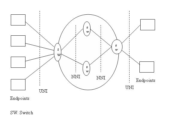
An ATM network of a set of ATM switches interconnected by point-to-point ATM links or interfaces. ATM switche support two primary types of interfaces: UNI and NNI.UNI(User Network Interface) connects ATM end systm to an ATM switch. NNI(Network-Network Interface) connects two ATM switches. Connection between two endpoints is accomplished through transmission paths (TPs), virtual paths (YPs), and virtual circuits (YCs). Architecture of an ATM network shown below,
ATM network
Architecture of an ATM network

Frame Relay Network

Frame relay is a high-speed Wide Area Network (WAN) protocol that operates at the physical and data link layers of OSI reference model. Frame relay originally was designed for use across Integrated Service Digital Network (ISDN). Some important features of frame relay are,
·        Operates in the physical and data link layers
·        Operates at a higher speed (1.544 Mbps and 44.376 Mbps).
·        Allows a frame size of 9000 bytes.
·        Less expensive as compare to other WANs
·        Frame relay detect errors at data link layer.
·        No flow control and error control
·        Is a virtual circuit network
·         Every virtual circuit in frame relay represent by using numbers that are usually known as data link connection identifier (DLCI).

X.25 Network

X.25 is an ITU-T standard protocol suite for packet switched wide area network (WAN) communication.  X.25 defines how connections between user devices and network devices are established and maintained. It typically used in packet switched networks of common carriers.
X.25 originally defined three basic protocol levels or architectural layers. In the original specifications, these were referred to as levels and had a level number, whereas all ITU-T X.25 recommendations and ISO 8208 standards released after 1984 refer to them as layers.

The following figure illustrates a typical X.25 network. X.25 network consist three typical components. DTE (Data Terminal Equipment), DCE (Data Communication Equipment) and PSE (Packet Switching Exchange). The user end of the network is known as Data Terminal Equipment and the carrier's equipment is Data Circuit-terminating Equipment. X.25 routes packets across the network from DTE to DTE by using Packet Switching Equipments. X.25 supports two types of virtual circuits, virtual calls (VC) and permanent virtual circuits (PVC). Virtual calls are established on an as-needed basis.

SONET

The uses of optical fiber cables for data transfer allow us to send data with high data rate. There exist two globally accepted standards for this type of high rate data transfer that are,
Synchronous Optical Network (SONET) developed by ANSI and
Synchronized Digital Hierarchy (SDH) developed by ITU-T
SONET defines a technology for carrying many signals different capacities through a synchronous, optical and flexible hierarchy. SONET/SDH is a synchronous network using synchronous TDM multiplexing. All clocks in the system are locked to a master clock. 
The following diagram depict a simple network using SONET,
A simple network using SONET equipment

Wednesday 9 January 2013

PSTN Switched Network

PSTN is an example of circuit switched network. The hierarchy of PSTN is shown below, 
PSTN hierarchy
PSTN hierarchy

Network Data gram Approach

In datagram approach to packet switching, each packet is transmitted independently from all other. This approach can cause the datagram’s of a transmission to arrive at their destination out of the order. The datagram networks are sometimes referred to as connectionless networks. A switch in a datagram network uses a routing table that is based on the destination address. Switching in the Internet is done by using the datagram approach to packet switching at the network layer.

Virtual circuit Approach

In the virtual circuit approach to packet switching, the relationship between all packets belonging to a message is preserved. A single route is selected between source and destination at the beginning of the session. When data are sent, all packets of the transmission travel one after another along the route. The packets may arrive at the destination with different delays if resource allocation is on demand. There exist two types of virtual circuit switching techniques switched virtual circuit (SVC) and Permanent Virtual Circuit (PVC).

Network Message Switching Techniques

In message switching instead of establishing a dedicated physical connection between source and destination, the message is sent to the nearest directly connected switching node. This node stores the message, checks for errors, select best available route and forwards the message to the next intermediate node. The line becomes free again for other messages, while the process is being continues in some other nodes. Due to the mode of action, this method is also known as store and forward technology.
Where the message hope from node to node to its final destination . each node stores the full message, checks for errors and forward it.

Basic Idea

·        Each node receives and store the message
·        Determine the next leg of the route
·        Queues the messages to go out on that line

Network Space Division Switching Techniques

In space division switching, the paths in the circuit are separated with each other spatially that is different ongoing connections at a same instant uses different switching paths, which are separated spatially. Crossbar switches and multistage space division switches are example of space division switching.

 Time division switching

Time division switches use time division multiplexing to achieve switching. There two methods used in time division switching: time slot interchange and TDM bus.

Time slot interchange (TSI)

We are using the following example to discuss TSI and TDM,
Assume that we have four nodes at sending side and four nodes at receiving. The nodes are labeled  as shown below,

Switching in Computer Networks

Whenever we have multiple devices, we have the problem of how to connect them to make one-to-one communication possible. One solution is to establish point-to-point connection between each pair of devices using mesh topology. However, mesh topology is impractical for large number of devices, because the number of links increases exponentially with number of systems. That means we need n(n-1)/2 connections to establish a mesh networks with n systems. A better alternative is the use of switched network. In this model, the network consists of a set of interconnected nodes among which information are transmitted from source node to destination node through different routes, which is controlled by the switching mechanism. A switched network consists of a series of interlinked nodes, called switches. There exist three methods of switching techniques: circuit switching, packet switching, and message switching.

Tuesday 8 January 2013

UGC NET Sample Questions

UGC NET Computer science June 2012

13.  Which layer of OSI reference model uses the ICMP (Internet Control Message Protocol)?
(A) Transport layer
(B) Data link layer
(C) Network layer
(D) Application layer

Answer: C

14.  Decryption and encryption of data are the responsibility of which of the following layer?
(A) Physical layer
(B) Data Link layer
(C) Presentation layer
(D) Session layer

Answer: c

UGC JUNE 2010

1. End-to-End connectivity is provided from Last-to-Last in
(A) Network layer (B) Session layer
(C) Transport layer (D) Data link layer
Answer: C


TCP/IP Reference Model

The TCP/IP protocol suite was developed prior to the OSI model. The original TCP/IP protocol suite was defined as having four layers: host-to-network, internet, transport, and application. As shown in the following illustration, each layer of the TCP/IP model corresponds to one or more layers of the seven-layer Open Systems Interconnection (OSI) reference model proposed by the International Standards Organization (ISO).
OSI and TCP/IP layers

Functions of OSI Layers Transport, Presentation session and Network

The basic function of transport layer is to accept data from the session layer and split it into smaller units, pass these to the network layer.
Other main functions of transport layer are
  • Connection control
  • Service point addressing
  • Segmentation
  • Reassembling
  • End to end error recovery and flow control

Session Layer

The session layer allows users to establish sessions between different machines. A session allows ordinary data transfer functions with some extended functionality.
Other functions of session layer are
  • Token management
  • Dialogue control
  • Synchronization 

Functions of OSI Layers Physical, Data Link and Network

The physical layer deals with the transmission of raw bits over a communication channel. It specifies the mechanical, procedural and electrical network interface specifications.

The major functions and services performed by the physical layer are
  • Decide signal level and data rate
  • Whether simultaneous transmissions in both direction
  • Deals with physical transmission of data
  • Determine number of pins and functions of each pins in the network connector.
  • Synchronization of bits
  • Determine transmission mode
  • Synchronization of bits
  • Representation of bits

There exists a variety of physical layer protocols such as RS-232, RS-449 standards developed by Electronic Industries Association (EIA).

Data Link Layer

The main goal of data link layer is to provide reliable, efficient communication between adjacent machines connected y a single communication channel.
Other responsibilities of the data link layer include the following:
  • Group the physical layer bit stream into units called frames (Faming)

OSI Layers

The Open Systems Interconnection (OSI) model (ISO/IEC 7498-1) describes how data from one application in one system moves through a network medium to an application in another system. It was developed in 1984. There are seven layers in OSI model. We will discuss functionality of each layer in following sessions.

The seven layers of OSI are,
1.      Physical layer
2.      Data link layer
3.      Network layer
4.      Transport layer
5.      Session layer
6.      Presentation layer
7.      Application layer

OSI Layers
Seven layers of OSI

Network Layered Architecture

To tackle with the design complexity most of the networks are organize as a set of layers or levels. The fundamental idea of layered architecture is to divide the divide the design into small pieces. The layering provides modularity to the network design. The main duty of each layer is to provide offer services to higher layers, and provide abstraction.  The main benefits of layered architecture are modularity and clear interfaces.
The basic elements of a layered model are services, protocols and Interfaces.

A service is a set of functions that a layer offers to another layer (usually to upper layer).
We know that protocol is a set of rules. Here the protocols are used to exchange information with a peer layer. Peers means layers at same level. The protocol consist several rules that deals with the content and the order or structure of the messages exchanged.  All the data from one layer to another either upper or lower layer pass through the corresponding interfaces. Suppose we have an n layered network then, layer-n of one machine take conversation with layer-n on another machine. Here layer-n protocol define the rules and orders.